
Identify Your Air-Conditioning System
Understanding your facility's air-conditioning equipment is the first step toward evaluating potential COOLNOMIX suitability and energy savings. Use the gallery below to recognize your system type, configurations and nameplate location.
Common Equipment Types
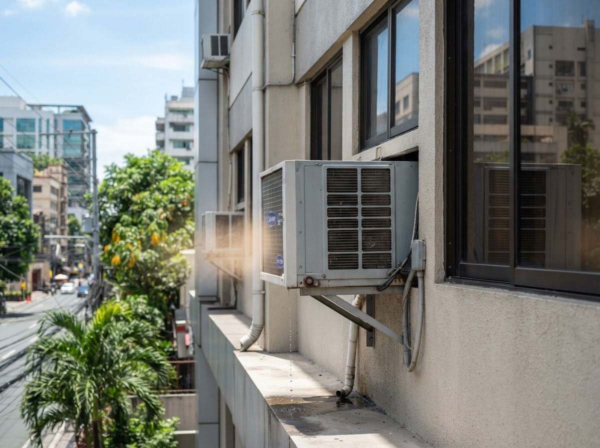
Window-Type AC
Self-contained unit mounted through a wall or window opening; evaporator, condenser and compressor in one chassis.
- Location
- Through-wall or window opening, single-room cooling.
- Compressor
- Hermetic rotary or reciprocating compressor.
- Indoor config
- Evaporator coil and fan within the chassis.
- Outdoor config
- Condenser coil and compressor within the same chassis.
- Nameplate
- Side or bottom panel of the chassis.
- Info needed
- Cooling capacity (HP or BTU/h), voltage, model and serial number.
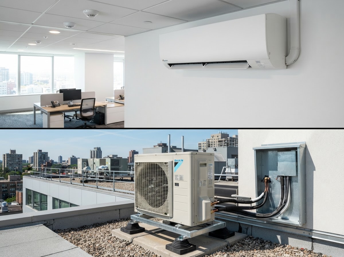
Wall-Mounted Split AC
Split system with a wall-mounted indoor fan-coil connected to a separate outdoor condenser.
- Location
- Indoor unit high on wall; outdoor condenser on bracket, ledge or roof.
- Compressor
- One compressor per outdoor unit (rotary or scroll).
- Indoor config
- Wall-mounted fan-coil with evaporator.
- Outdoor config
- Condenser unit with compressor and condenser coil.
- Nameplate
- Side panel of the outdoor condenser unit.
- Info needed
- Capacity, refrigerant type, voltage, indoor and outdoor model numbers.
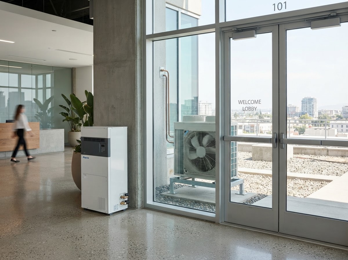
Floor-Standing Split AC
Split system with a floor-mounted cabinet indoor unit and a separate outdoor condenser.
- Location
- Indoor cabinet on the floor; outdoor condenser elsewhere.
- Compressor
- One compressor per outdoor unit.
- Indoor config
- Floor-standing cabinet fan-coil unit.
- Outdoor config
- Separate condenser unit with compressor.
- Nameplate
- Side panel of the outdoor condenser.
- Info needed
- Capacity, refrigerant, voltage, model numbers.
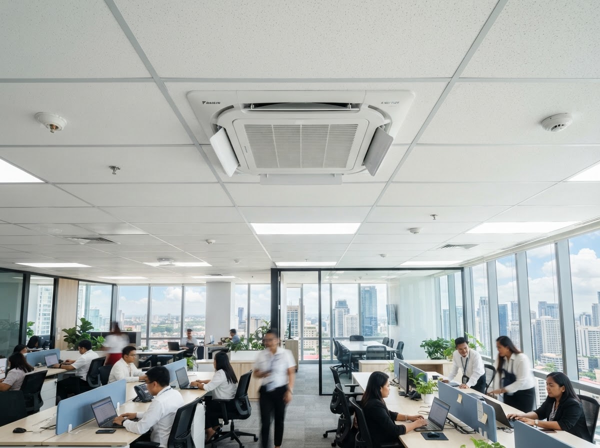
Ceiling Cassette AC
Split system with a ceiling-recessed cassette distributing air in multiple directions.
- Location
- Ceiling-recessed in a suspended ceiling grid.
- Compressor
- One compressor per outdoor unit.
- Indoor config
- Cassette fan-coil unit in the ceiling.
- Outdoor config
- Separate condenser unit, often on the roof.
- Nameplate
- Side panel of the outdoor condenser.
- Info needed
- Capacity, refrigerant, voltage, model numbers.
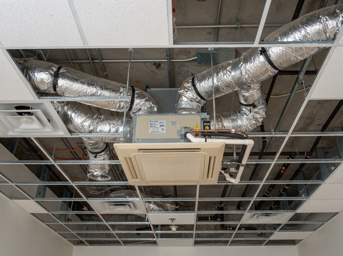
Concealed Ducted Split AC
Split system with a concealed ducted indoor unit supplying air through ductwork and grilles.
- Location
- Indoor unit in a ceiling plenum; ducted to ceiling or wall grilles.
- Compressor
- One compressor per outdoor unit.
- Indoor config
- Ducted fan-coil concealed above the ceiling.
- Outdoor config
- Separate condenser unit.
- Nameplate
- Outdoor unit panel and indoor unit nameplate.
- Info needed
- Capacity, refrigerant, external static pressure, voltage, model numbers.
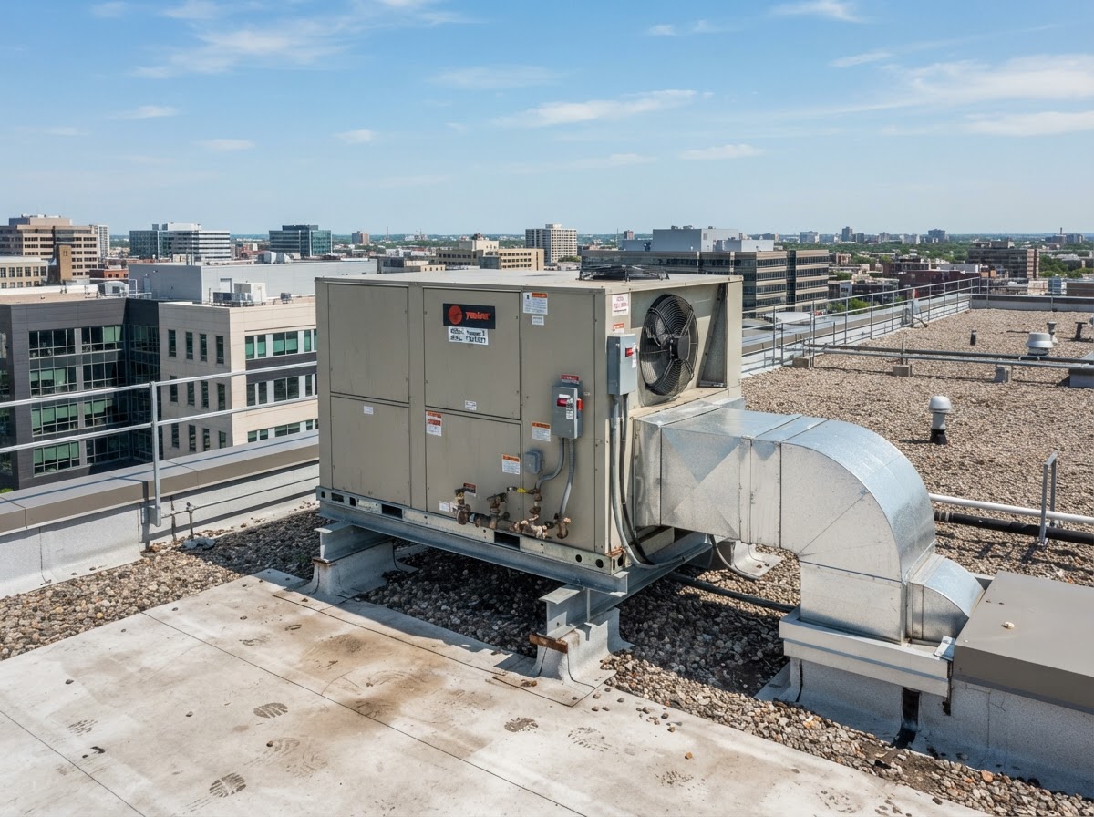
Packaged DX Units
Self-contained direct-expansion unit with all components in one cabinet, ducted to the space.
- Location
- Ground-mounted, wall-mounted or rooftop; ducted to interior.
- Compressor
- One or more compressors within the cabinet.
- Indoor config
- Supply and return duct connections to the building.
- Outdoor config
- Condenser section and compressor within the same cabinet.
- Nameplate
- Access panel on the cabinet.
- Info needed
- Capacity, refrigerant, voltage, model number.
Rooftop Packaged Units
Self-contained packaged unit mounted on the roof, serving the floor below via ductwork.
- Location
- Rooftop curb mounting; ducted down through the roof.
- Compressor
- One or more compressors (often scroll).
- Indoor config
- Ducted supply to the floor below.
- Outdoor config
- Entire unit on the roof; condenser and compressor inside.
- Nameplate
- Access panel on the unit.
- Info needed
- Capacity, refrigerant, voltage, model and serial number.
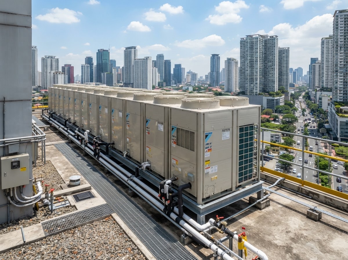
VRV / VRF Systems
Variable refrigerant flow system with many indoor units connected to one or more outdoor condensing units.
- Location
- Indoor units throughout the building; outdoor units on roof or plant deck.
- Compressor
- Inverter-driven compressors in the outdoor unit(s).
- Indoor config
- Many indoor units (wall, cassette, ducted) on a common refrigerant circuit.
- Outdoor config
- One or more modular outdoor condensing units.
- Nameplate
- Each outdoor condensing unit.
- Info needed
- Indoor-unit count, compressor count, refrigerant, voltage, model numbers.
DX Air-Handling Systems
Direct-expansion air-handling unit with a cooling coil connected to a remote condensing unit.
- Location
- Mechanical room or ceiling; ducted to multiple zones.
- Compressor
- Compressor in the remote condensing unit.
- Indoor config
- Air handler with a DX coil and supply fan.
- Outdoor config
- Remote condensing unit with compressor.
- Nameplate
- Air handler and the condensing unit.
- Info needed
- Coil capacity, refrigerant, airflow, voltage, model numbers.
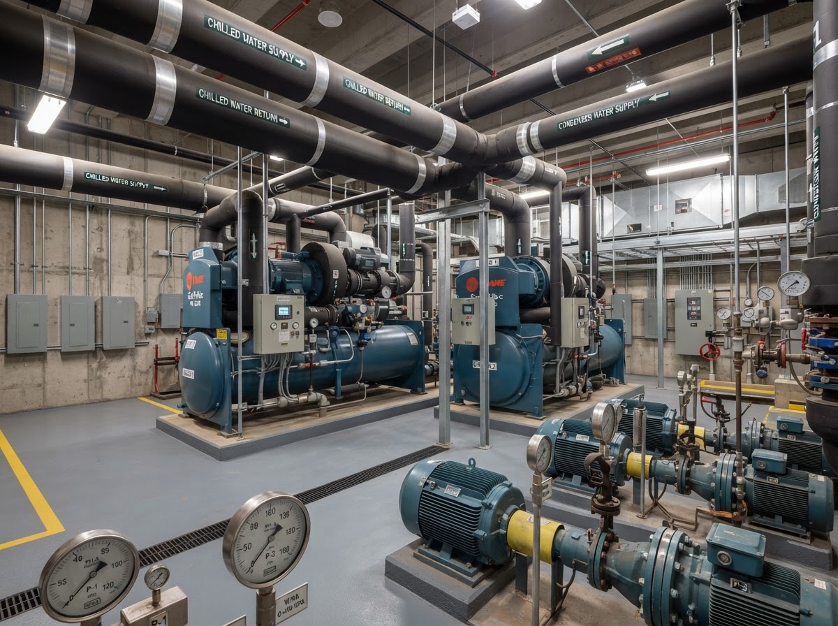
Central Chilled-Water Plants
Central plant producing chilled water distributed to multiple air-handling units.
- Location
- Central plant room; chilled water piped to AHUs throughout the building.
- Compressor
- Compressors within the chiller(s).
- Indoor config
- Air-handling units with chilled-water coils.
- Outdoor config
- Chiller(s) with compressors in the plant room or on the roof.
- Nameplate
- Each chiller unit.
- Info needed
- Chiller capacity, compressor type, refrigerant, voltage, model numbers.
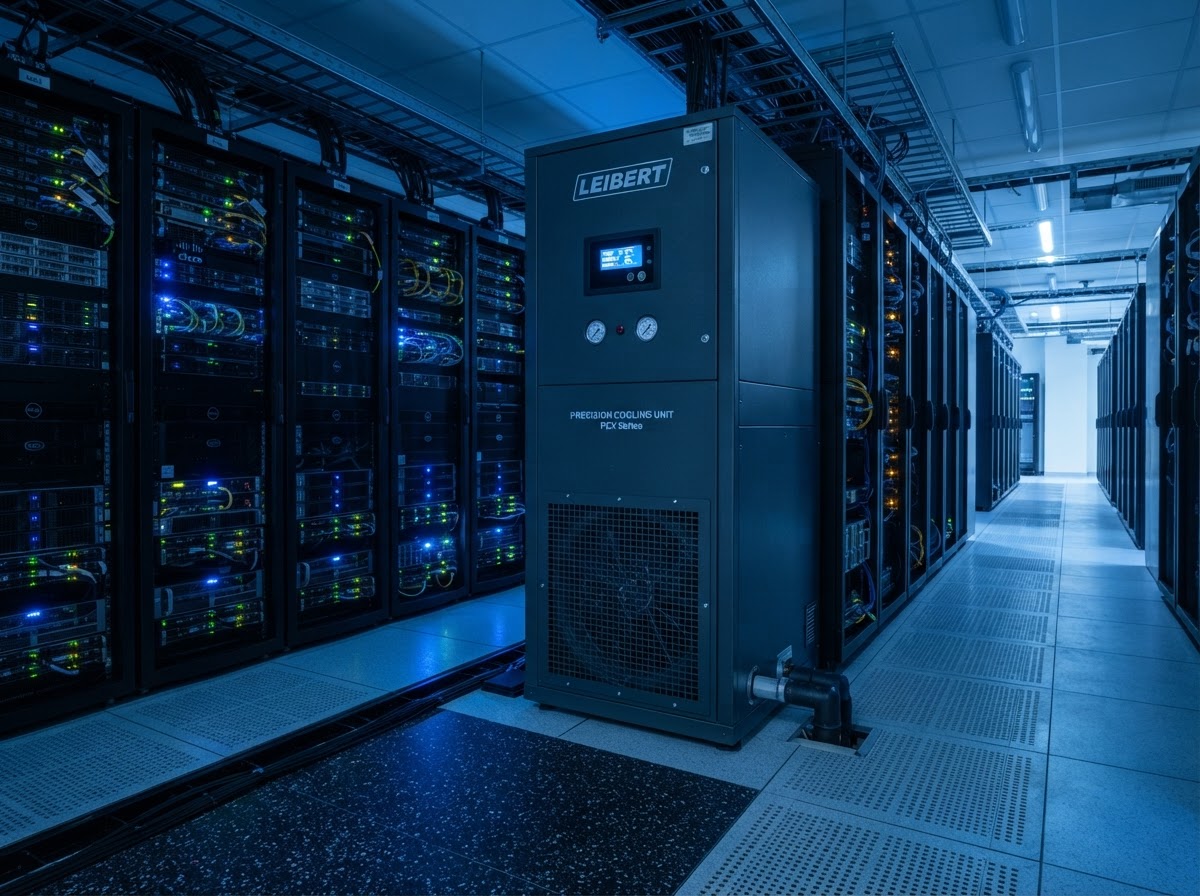
Precision Cooling Systems
Close-control air-conditioning for spaces requiring tight temperature and humidity, such as server rooms.
- Location
- In-room or adjacent precision cooling units.
- Compressor
- Compressor(s) per configuration (often scroll).
- Indoor config
- Precision cooling unit with a DX or chilled-water coil.
- Outdoor config
- Condensing unit or chiller, as configured.
- Nameplate
- Precision cooling unit nameplate.
- Info needed
- Sensible and total capacity, refrigerant, voltage, model numbers.
Manufacturers such as Daikin, Carrier, Trane, Mitsubishi Electric, LG and Panasonic are referenced as equipment-identification examples only. No endorsement of COOLNOMIX by these manufacturers is implied. Photographs are representative illustrations of equipment categories, not specific installations.
Indoor Units ≠ Compressors ≠ AC-01 Units
Indoor-unit quantity is not necessarily equal to compressor quantity, and compressor quantity is not necessarily equal to the number of AC-01 units that may be suitable. A VRF system, for example, may have many indoor units served by a smaller number of outdoor compressors. A technical review of compressor and independently controlled control-circuit configuration is required before any provisional AC-01 quantity can be proposed.
AC-01 Installation Concept
The diagram below shows the conceptual relationship between the existing HVAC system, the compressor and control equipment, a potential AC-01 control integration point, metering equipment and facility energy consumption.
Conceptual illustration only. Not an installation or wiring instruction. Detailed installation wiring and sensor placement are not shown and require current manufacturer-approved documentation and qualified personnel.